Showing posts with label Lesson 1. Show all posts

Friday, 8 May 2015

Lesson 1 > 8 > Plotting in AutoCAD

1.8.1 Introduction

When you complete your work gets complete you want to share it with the other people. You dont know whether he has AutoCAD or not so you prefer to share it in the image or in the solid copy i.e. in the printed format. For that you need to give AutoCAD a command for printing. This is done by plotting a drawing. In one sheet of AutoCAD their are multiple drawings and AutoCAD don't understand which drawing he has to print. So, that time we need to provide the AutoCAD the area which we want to be get printed. That process is called as plotting.

1.8.2 Plotting A Plan

We have seen why we need to plot. Actually plotting is noting but providing two co-ordinates. The co-ordinates are such that the area between those points gets printed. So we will try to print a object placed between the red lines in the image below.
Figure 1.8.1 : Plan to be printed
Steps:
  1. Now we have to print the plan in the red box. For that first we go to Application Menu > Print > Plot
    Figure 1.8.2 : Position of the Plot Button.
  2. After selecting the Plot option it will open a window like in the image below.
    Figure 1.8.3 : Plot Window
  3. Now we have to select the area to be printed for that click on the " Window< " button if the button is not available in the Plot Area from dropdown select Window option.
    Figure 1.8.4 : Plot Area
  4. After click on the "window <" the window will be gone and you are asked for the area you want to print. Then select the area which we want to printed the same way we create a rectangle in AutoCAD.
    Figure 1.8.5 : Selecting Plot Area
  5. Now you have provided the area to AutoCAD which you have to print. The Next thing is to print it as we do it regularly.

Lesson 1 > 7 > Hatching Property in AutoCAD

1.7.1 Introduction

Now we have created the object inside AutoCAD. We have given them dimension now the only thing remaining is that we need to add some filler in it. Some of the hatching work is missing in the drawing. So, the next thing we all are going to do is we are going to add hatching to the object.

1.7.2Adding Hatching

Adding hatching to the drawing is a simple task. For that you need to select the object then we need to select the type of fill and the objects in which the hatching work is to be done.
Hatching can be only applied to object which is enclosed by four side.
Steps:
  1. To add the hatching to the drawing first we need to create a enclosed boundry. You can use the previous drawings in which we have created the square and circle.
  2. Now click on the hatch icon [  ] or use the command HATCH
  3. Now Select the objects in which you have to add the hatching and press enter. It will create some hatching in the filling. It might not be as you supposed but the next point in this chapter will help you to edit this hatching.

1.7.3 Editing Hatching

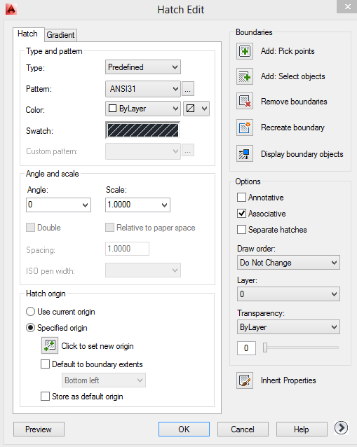
Recently we have applied the hatching to the object but we need to customize it as per our need. for that click on the hatch edit icon [ ] or use the command HATCHEDIT . After that select the hatch you want to edit.which will open a popup window as shown in figure 1.7.1
Figure 1.7.1 : Hatch Edit window
In the above window you have seen some options which are described below:
Color : To change the color of the hatching.
Swatch : To edit the filling pattern in the object. Clicking on the swatch will open a new popup from where the proper hatching can be selected.
Angle: To setup the inclination of the hatching. The angle of the hatching.
Scale: The size of the hatching inside the object can be maintain with the scale.
Add Pick Points : To insert same hatching in the new object.
Remove Boundry : To remove the hatching from any object.

1.7.4 Adding Gradient

Previously we have added the hatching in the object now we will try to add the gradient inside the object. for that there are some simple steps:
  1. Add the hatching the same way we have added earlier and click on the edit hatch.
  2. On the top there is the option of hatching as shown in figure 1.7.2
    Figure 1.7.2 Adding gradient
  3. Now select the two colors from which you have supposed the gradient  and click on the OK.
  4. The gradient hatching is applied to the object.

AWESOME TIP
While adding hatching to each object you need to repeat the same command again and again. The shortcut for the recent command is pressing the "ENTER" button twice.

Lesson 1 > 6 > Layers in AutoCAD

1.6.1 Introduction

When we all go to shop there are various parts. In each part we get the different things.In the food section we get all the eatable things whereas in the clothing section we get cloths. The same way in AutoCAD we can crate a group of the objects which is called as layers. For each layer we can assign the different color and we can hide and show this group in unity. Suppose we are going to create a plan then we will create different layers. say one layer is of brickwork, one is of furniture and so on.

1.6.2 Creating a Layer

Well now you have seen the importance of layer. Now we will try to create the layer. Creating a layer is an easy task. Now we will see how to create a layers in AutoCAD.
Steps:

  1. For creating a layer use command LA or LAYER in the command box.
  2. After inserting the command you will see a popup window which is looking somewhat in the figure 1.6.1
    Figure 1.6.1 : Layers Window
  3. The details of the each icon and their result is given in the table below.
    Icon Name Command Result

    New Layer
    ALT + N
     It is used to create a new layer with the unique name.

    Layer Setting
    -
    To edit the settings of the layers.
    Delete Layer
    ALT + D
    To remove/delete the layers.
    Set Current
    ALT + C
    To Apply the layer. So that the new object created will be automatically introduced in this layer.
  4. Now create a new layer using the button or use the command ALT + N. With this you will see there is new line created in the list of layers assign it with the proper name and select the suitable color for it.
    Figure 1.6.2 : Selecting color for the layer
  5. Now select the set current button so that the new objects you draw will become the part of that layer.


1.6.3 Hiding and Locking a Layer

While creating a new layer you have seen some of the icons in front of created layers. One is of the Light and another is of the lock. But why these icons are provided? What is the use of that icon? The Fucnction of the buttons is given in tha table below.
Icon Function

It show/hide the layer. Which helps in the better understanding when there are lot's of objects overlapping on each other.

It Enables/Disables the editing of the objects in the layers.

Lesson 1 > 5 > Dimensioning & Text in AutoCAD

1.5.1 Introduction

As we have created the various objects, learned most of the modification command the next thing we need to understand is adding the dimensions inside the drawing. Even we will also try to add some of the text inside the drawing. Adding the text and dimension helps people to understand the sizes of rooms and without the naming the person gets confused. So, it is must to provide the proper dimension and text in AutoCAD. Same we will try to add the dimension to the drawing.

1.5.2 Adding Dimension

In chapter 2 we have created a circle and square and we haven't given dimensions to them so now we will try to give the dimension to the previous drawings. Our created drawing that time is some what like given below:
Figure 1.5.1 : Dimension Assignment
 If you have forgot to save that file then you can download it from here: Dimension Assignment.dwg
Steps:
  1. Open the drawing file provided or you have created in the chapter 2.
  2. Now we have to give the dimension for that go to Annotate tab > Dimension.
    Figure 1.5.2 : Dimension Panel
  3.  In the dimension panel you will see the dropdown where the various options are given. The options are described in the table below:
    Icon Name Command Use

    Linear
    _dimlinear
    Creates a linear dimension with the straight, rotated or inclined line.

    Aligned
    _dimaligned
    To give linear dimension to the inclined line.

    Angular
    _dimangular
    To give the angular dimension between to lines.

    Arc Length
    _dimarc
    To give the arc dimension.

    Radius
    _dimradius
    To create a radius dimension to the circle object.

    Diameter
    _dimdiameter
    To create a diameter dimension to the circle.

    Jogged
    _dimjogged
    To create a jogged dimension for the circle and arc.

    Ordinate
    _dimordinate
    To create a co-ordinate dimension point of the object.
  4. Initially we want to give the dimension to the square for that we will use linear dimension and in case of the circle we will use diameter.
  5. For linear dimension click on the linear dimension button or use command _dimlinear and select the starting and ending point.
    Figure 1.5.3 : Adding linear dimension
  6. Same for the circle use diameter command and select the circle.
    Figure 1.5.4 : Adding Circular Dimension

1.5.3 Adding Text

We have added the text inside the drawing but it is not at all sufficient to get the work done. We also need to add text at some places in the drawing. So we will try to add the text below the objects in the previous drawing. i.e. we will add "Square" below the square object and "Circle" below the circle object. Adding the text is quite easy.
Steps:
  1. To add text inside the document go to Annotate Tab > Text as given in following figure.
    Figure 1.5.5 : Adding Text
  2. There you will find two types of text one is of the single line whereas the another is of the multi-line. 
  3. To create the text object select one of it and make the rectangular area where we are supposed to add the text. In our case we need to add the text below the square.
    Figure 1.5.6 : Selecting Text area
  4. After creating the text area you need to add the text in the same manner as we do in the MS paint. But while writing you may get very small or big font and improper alignment which can be maintain by the editing option which appear while writing the text.
    Figure 1.5.7 : Editing Function
  5. When you change the font size and other data and feel comfortable repeat the same procedure and add the text below circle. and your final work will look something like given below.
    Figure 1.5.8 : final result


Thursday, 7 May 2015

Lesson 1 > 4 > Adjusting Object Snap & Status Bar Function in AutoCAD

1.4.1 Introduction

What the main problem you have faced while plotting a line? or intersecting a line? Your lines might not be straight and might not be netting at a center part. Else it is hard to find the center of the line while plotting another one. Don't Worry Object Snaps and other functions Enables us to easily do the same work in AutoCAD. All we have to do is arrange them perfectly. Let's arrange your object snaps in the perfect way.

Status Bar Functions

Status bar has various icons and it's icon have their own function. The following table will help you to easily understand them.
Icon Name ShortCut Function

Grid F7 Display the Graph format on the background of the workspace.

Ortho F8 Helps to draw the line parallel to the axis.

Polar Tracking F10 Measures the angular measurement of the segments.

Object Snap F3 Show the corners, midpoint of the 2d objects.
as you have understood the working of the each function in the Status bar. The next main thing you need to customize is the Snaps. The above shortcut given above only turn on and of the snaps of the object don't allow to customize them.

1.4.2 Customizing Object Snap

Customizing the object snap is one of the necessary thing after installing the AutoCAD. It helps us to link the Corners, Mid-Points of the objects while creating the line segments. So, it is must for everyone to customize it as per the need. To customize the object snap right click on the snap icon in the status bar. and select the option settings.
Figure 1.4.1 : Opening Settings of Snap
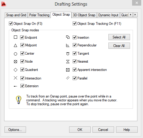
After going to settings a new dialouge box will appear with lot's of tickmark boxes. in which tick all the boxes for better workflow.

Figure 1.4.2 : Object Snap Settings


Lesson 1 > 3 > Modification Commands in AutoCAD

1.3.1 Introduction

In the previous lesson we have seen some of the basic commands which enables us to draw the object. Now we will try to modify the objects with most advanced commands. In previous chapter you have learned about drawing the circle and rectangle now we will focus on editing those. We will try to trim a line and to extend it. Even we will also try to erase, placing the objects and making the multiple copies of it. And at last we will try to move the object from it's original location.

1.3.2 Modify Commands

The section you can find at the HOME tab. There is a separate panel of the modification commands. There are number of modification commands describe in detail below :

Icon Function Command Location Result

Trim
TRIM
Home > Modify > Trim Trim the object to match the edge of another object.

Extend
Extend
Home > Modify > Extend Extend the object to meet the edges of another object.

Offset
O / Offset
Home > Modify > Offset To draw Parallel line at particular distance.
Copy
_copy
Home > Modify > Copy To create multiple copies from a single object.

Mirror
_mirror
Home > Modify > Mirror Creates mirror copy of the selected object.

Erase
_erase
Home > Modify > Erase To remove the object.

Move
M / _move
Home > Modify > Move To move the selected object to new co-ordinates.
As like the previous chapter we will also do some of the practical work for easy understanding of the each command. we try to create the following work (need not be done as per dimension.):
Figure 1.3.1 : Modification Commands Assignment
The procedure of doing the drawing is :
  1. First draw a line segment of any length you suppose.
    Figure 1.3.2 : Draw a line
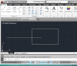
  2. Now create a rectangle of any size but it must be over the line.
    Figure 1.3.3 : Draw a rectangle over a line.
  3. Now we have to remove the line inside the rectangle so we will use the trim command. For that first select the whole drawing and click on the trim icon or use TRIM command in the command box. 
    Figure 1.3.4 Applying Trim
  4. Now click on the line inside the rectangle and you will see it is disappeared. 
    Figure 1.3.5 After using Trim
  5.  Now we have used trim to remove the excess line now we want to mirror the whole drawing for that again select the whole drawing and click on the mirror icon. 
    Figure 1.3.6 Selecting whole drawing for mirror
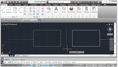
  6. Mirror command is not applied yet. For applying the mirror command draw a invisible line by clicking at right keeping some space. And when you feel comfortable with it press ENTER .
    Figure 1.3.7 Creating invisible line while using Mirror.
  7.  Now you have created a object with mirror and your work is looking somewhat like in the image below.
    Figure 1.3.8 : object formed after mirror
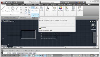
  8. The next command we are going to use is extend it is almost same as trim. Again select the whole mirrored side object and click on the extend icon. After that click on the line which we want to extend. And with ease it will be extended upto the next line perpendicular to it.
    Figure 1.3.9 : Using Extend Command
  9. Now, we have used the Extend command the next command we are going to use is OFFSET command. For that select the line segment and asususal click on the offset icon. The next thing we need to provide is the distance between the line which we are going to form. Put the value with respective size not too big and not too small. and once you place all that you need to select the side on which you want the parallel offset to be made. to click on the top most side of the line. and your work will look like the one given in the image below.
    1.3.10 : Object formed using offset command.
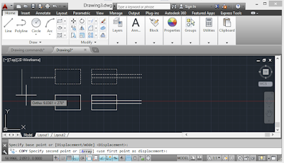
  10. Now our object is almost formed and just one step away. The next command we are going to use is COPY . With the help of these command we will create copy of the same object just below it. For that select your whole work and click on the copy button or directly use the COPY command in the command box. Now in the workspace click at any point and move your mouse towards downside. You will see the same invisible line as in the case of the mirror. Move the mouse down until it comes down from the previous object.
    1.3.11 : Creating object using COPY
  11. Now you have created the object successfully. You have used almost every modification command in this. Try using all of the drawing and modification commands yourself to create a new and ridiculous objects. The more you practice the more perfect you become with it.
AWESOME TIP:
When you are using TRIM command you can directly switch to extend by just pressing the SHIFT button. Instead of again selecting the whole object. [Reversal for Extend]


biz.